24th Feb. Added a movie. The signal is displayed on the LCD of the board. The waveforms are written for the time being, but it still seems to take a while for fine-tuning. There is also a fairly large electrical noise. After that, the noise was removed by reducing the magnification. Added a video to measure the sampling rate. The sampling rate was surprisingly high! I just checked the Ali dealer and found that the price was only 2200 yen including shipping, so I immediately ordered more. https://www.aliexpress.com/p/trade/confirm.html
 |
 |
| 今
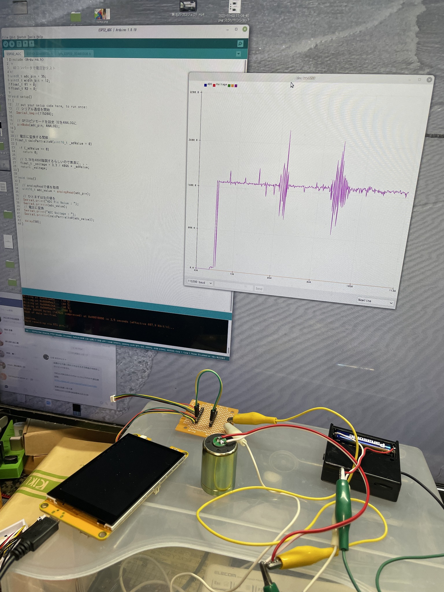
日の朝からの開発全景.ESP32内蔵のAD変換機能で,振動センサからの信号を表示.プログラムはネットで拾ったごく簡単なもの.ESP32基板に取り
込んだ信号をArduinoIDEで処理して,シリアルプロッタにグラフ表示.短いプログラムでしょ!これだけで簡易地震計が一丁上がり!ただし,基板の
方のLCDモニタに表示や,データのSDカード保存などは,まだこれからの課題.明日以降の作業となる. The signal from the vibration sensor is displayed by the built-in AD convertor of ESP32. The program is a very simple one that I found on the Internet, and it processes the signals imported into the ESP32 board with ArduinoIDE, and displays them graphically on a serial monitor. It is a short program, isn't it? This is all you need to create a simple seismograph! However, displaying the data on the LCD monitor on the board and saving the data to the SD card are still to be done. This work will be done tomorrow or later. |
な
んかすべてはうまく行ってことのほか,不思議なほど.当然ながらESP32のADC入力は正電圧対応だけなので,電池(1.5V)で振動センサの出力(つ
まりADCの入力)にバイアスをかけることを考えた.手持ちの百均安物アンプの,単4電池ホルダに無理やりハンダ付けして,+1.5Vを取り出し,振動セ
ンサの出力をかさ上げするという,簡単な回路.これだけで振動センサの出力が0〜3.3Vの範囲内に収まり,きちんど波形を書いてくれる.我ながらなかな
かのアイデアと自画自賛.本家Raspberry
Shakeもびっくりという簡易仕様.
Naturally, the ADC input of the ESP32 is only for positive voltage, so I thought of using a battery (1.5V) to bias the output of the vibration sensor (i.e., the input of the ADC). A simple circuit that forcibly solders a battery holder on a cheap amp I have on hand, extracts +1.5V, and raises the output of the vibration sensor. With this simple circuit, the output of the vibration sensor is within the range of 0 to 3.3V, and the output waveform is properly displayed. I am quite proud of this idea. Even the original Raspberry Shake was surprised at this simple specification. |
 |
 |
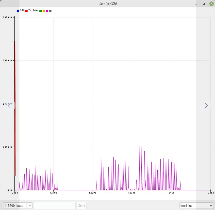
| これが最初電池のバイアスをかけずに,振動センサの出力を表示したところ.正の電圧のみが表示される.しかもこのときは,プログラムが1秒おきの入力制限で調子がおかしかった. |
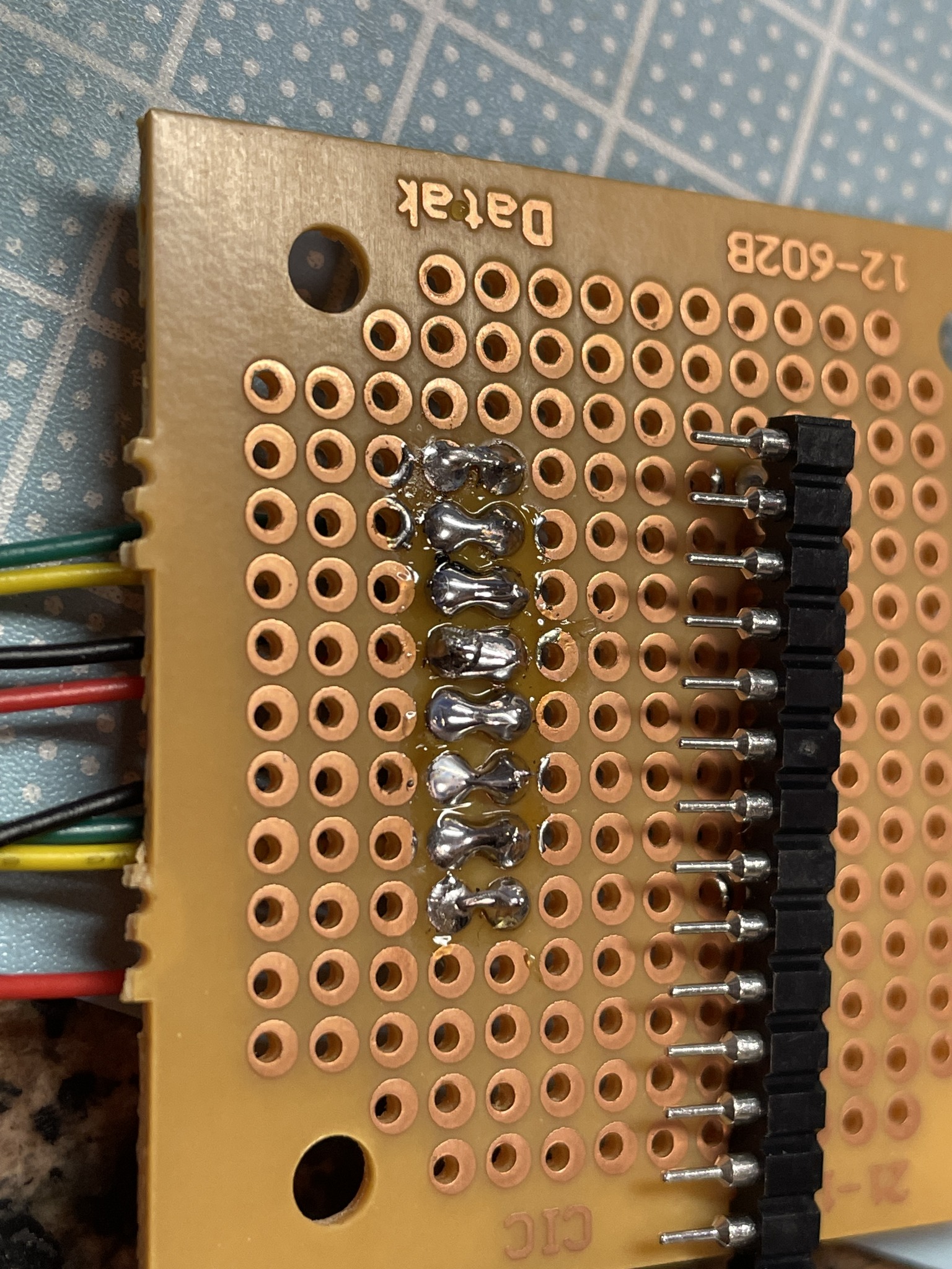
ESP32のADC入力に信号を入れるための補助基板をハンダ付け.といっても写真のピンを8pinのところで割って,ハンダ付けしただけ.なかなかうまくできた. |
 |
 |
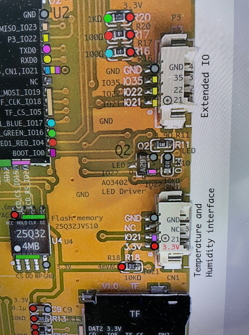
| ESP32のADC入力はネットで調べて,ごらんのIO35だと目星を付ける.これととなりのGNDの間に信号を入れる回路を作る.このソケットとケーブルは,1.25mmピッチ4Pとやや特殊なので,AliExpressで入手.
I found the ADC input of ESP32 from the Internet, and found it is IO35 as you see in the figure. I made a circuit to insert a signal between this and the GND next to it. The socket and cable are 1.25mm pitch 4P and somewhat special, so I got them from AliExpress. |
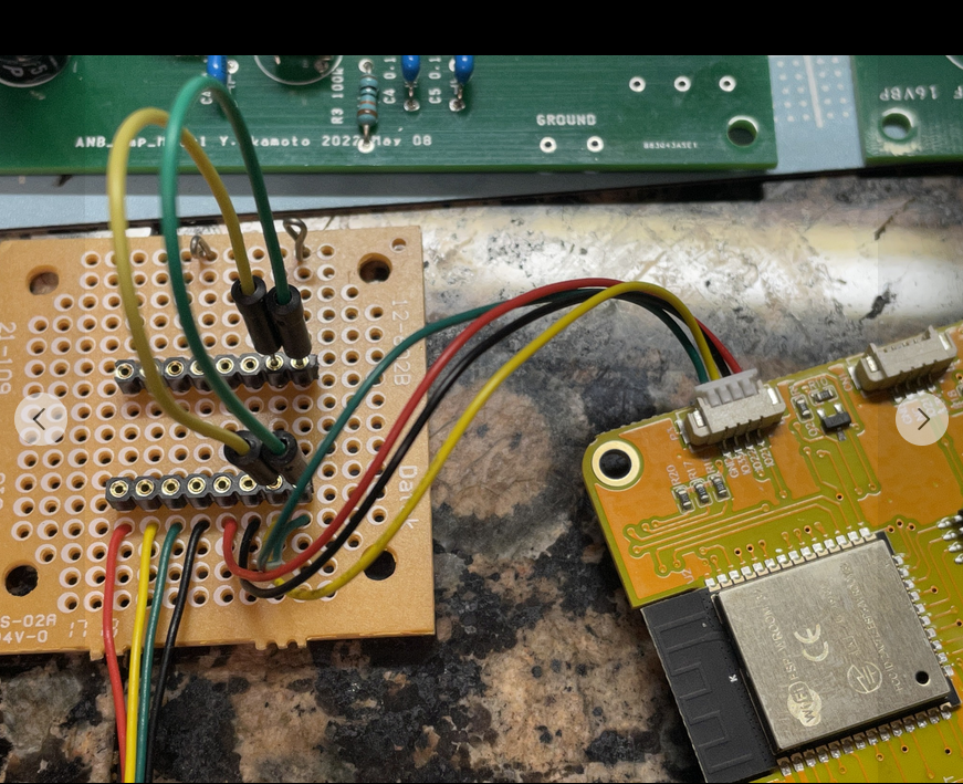
こ
れが完成品.基板から1.25mmピッチの4Pソケットで信号を基板に入れる.振動センサからの信号は,基板向こう側のむき出しの2つのピンにみの虫ク
リップで入れる.超簡単設計.振動センサは電源不要なので,基板のもう一つの拡張端子(写真右端)は使わずにすんだ.信号は補助基板の黄色(GPIO35
端子)と緑(GND端子)のジャンパー線を通る.赤と黒は配線しているものの使用せず.あとはArduinoIDEでピン番号を指定するだけで,動画のよ
うに信号が表示できる.(2024-02-23.追記,ESP32本体のICに,技適マークがちゃんと印字されていることに注意)
Signals from the board are inserted into the board using a 1.25mm pitch 4-pin socket. The signal from the vibration sensor is inserted into the two bare pins on the other side of the board using worm clips. Super simple design. The vibration sensor does not require a power supply, so the other extension terminal on the board (far right in the photo) is not used. The signal goes through the yellow (GPIO35 pin) and green (GND pin) jumper wires on the auxiliary board. Red and black lines are wired but not used. The signals can be displayed as shown in the movie by specifying the pin numbers in ArduinoIDE. (2024-02-23. Note that the Japanese technical certification mark "Giteki技適"is printed on the ESP32's IC.) |
 |
 |
| しかし振動センサ単体ではおそらく感度不足なのを見越して,アンプの製作を平行してハンダ付け.これ昔地震学会の広報紙に書いた回路を,https://www.zisin.jp/publications/pdf/nf-vol103.pdf#page=6 中国格安基板メーカーにCADデータ送って外注したもの.1枚200円もかからなかった.朝からとりあえず1枚ハンダ付け終了.2ch分のうち1chを使用予定.OPアンプであるが5V片電源(USBからとる)で使えるはず.これは明日以降の作業. However, I anticipated that the sensitivity of the vibration sensor by itself would probably be insufficient, so I soldered an amplifier in parallel with the construction. This is a circuit I wrote for a newsletter of the Seismological Society of Japan in the past. I sent the CAD data to a cheap Chinese circuit board maker and outsourced the work, which cost less than 200 yen per piece. One of the two channels will be used, and although it is an OP amp, it should be usable with a 5V single power supply (from USB). This work will be done after tomorrow. |
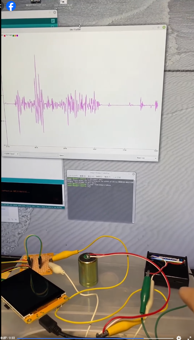
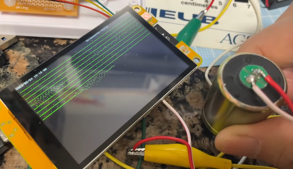
とりあえず,LCDに信号を表示させています.感度はまだ小さいですが,周期的に細かい電気的ノイズ?が確認されます.タイムマークやサンプリング速度の確認,アンプとの接続,SDカードへのデータ保存など,まだまだこれから課題山積です.
For the time being, the signal is displayed on the LCD. The sensitivity is still small, but periodic small electrical noises can be confirmed. There are still many issues to be solved, such as checking time marks and sampling speed, connecting to an amplifier, and saving data to an inner SD card. |
 |
 |
| 続
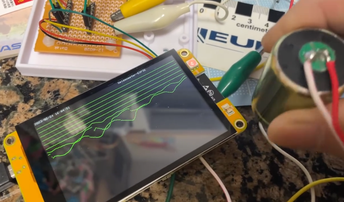
いてもう1本動画.信号の拡大率を抑えて,タイムマーク(秒)を入れてみました.横480ピクセルを現在20秒ほどで横切る計算です.24Hzくらいのサ
ンプリングに押さえています.フリーランなら48Hz行けそうです.これなら微小地震の観測にも十分です.ADCだけだと意外と画面書きながらでも,高速
サンプリング可能だとわかりました.前の微気圧のときは,センサを叩きにいく必要があり,サンプリングレートが抑えられていました.文献:岡本義雄:Raspberry Piと高感度気圧センサを用いた微気圧計の製作,日本地学教育学会第76回島根大会,2022
English_ver Poster
Here is another video. I reduced the magnification rate of the signal and added a time mark (in seconds). It currently takes about 20 seconds to cross 480 pixels horizontally. 24Hz sampling is used. Free-run mode can go up to 48Hz. I found that ADC alone can sample at high speed while writing on the screen. In
the previous microbarometer, the sampling rate was suppressed because
of the slower sensor reaction speed of microbarometer IC tip. |
プ
ログラムにdelay()を入れずに,フリーランニングでどれくらいのサンプリング速度になるかをチェック.驚いたことに,LCD横幅一杯,およそ
480Hzでサンプリングが可能だとわかりました.恐るべしESP32+LovyanGFX.これで微小地震関係(10Hz以下の振動)の高速サンプリン
グも問題なし!とはSDにデータ書き込みながらとかで,どれくらいレートが落ちるか.
We checked the sampling rate by free-running without delay() in the program. To my surprise, I found that I could sample at about 480 Hz, the full width of the LCD. With this, high-speed sampling of microseismic data (higher than 10 Hz) is no problem! I wonder how much the sampling rate will drop while writing data to SD. |
2023年2月25日 ·
February 25, 2023
ESP32 地震計プロジェクト.何とか試作版が完成近くなりました.今朝からアンプをつないだのですが,最初ノイズがひどく実用になりません.色々考えてデータの移 動平均を取ることにしました.写真で説明します.これでアンプを最高感度にすると,すぐ近くの電車の振動も拾えるようになりました.何とか実用になりそう です.少しこのままで自然地震の記録が採れるのを待ちます.ノイズはネット検索によると,この基板では仕方ないらしいです.解決策は今のところデータの移 動平均か,基板の電源とAD入力へのコンデンサ付けらしいのですが,ちょっと基板ハンダ付は忌避して,とりあえずの備忘録です.ノイズの件はたとえば
https://kohacraft.com/archives/202202081752.html
I have managed to get the prototype version close to completion. I connected the amplifier this morning, but at first the noise was so strong that it was not practical. After much consideration, I decided to take a moving average of the data. I will show some figures. When the amplifier is set to the highest sensitivity, it can even pick up the vibration of a nearby train. It seems to be useful. I will wait for natural earthquake recordings to be taken. Noise seems to be unavoidable with this board, according to an Internet search. The solution is to add capacitors to the power supply and AD input of the board, or to transfer the average of the data. For noise, see for example https://kohacraft.com/archives/202202081752.html
 |
 |
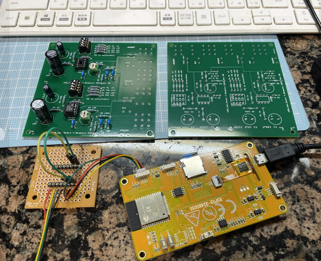
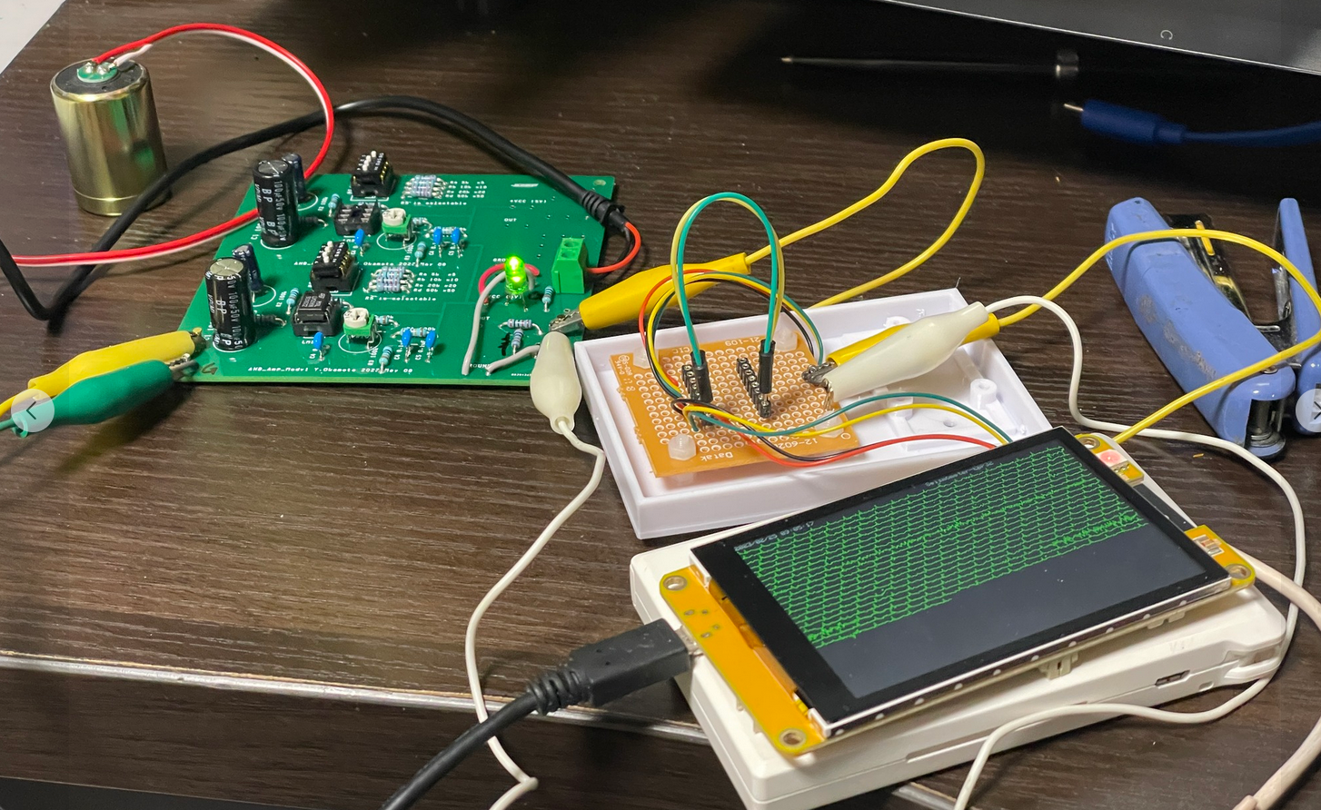
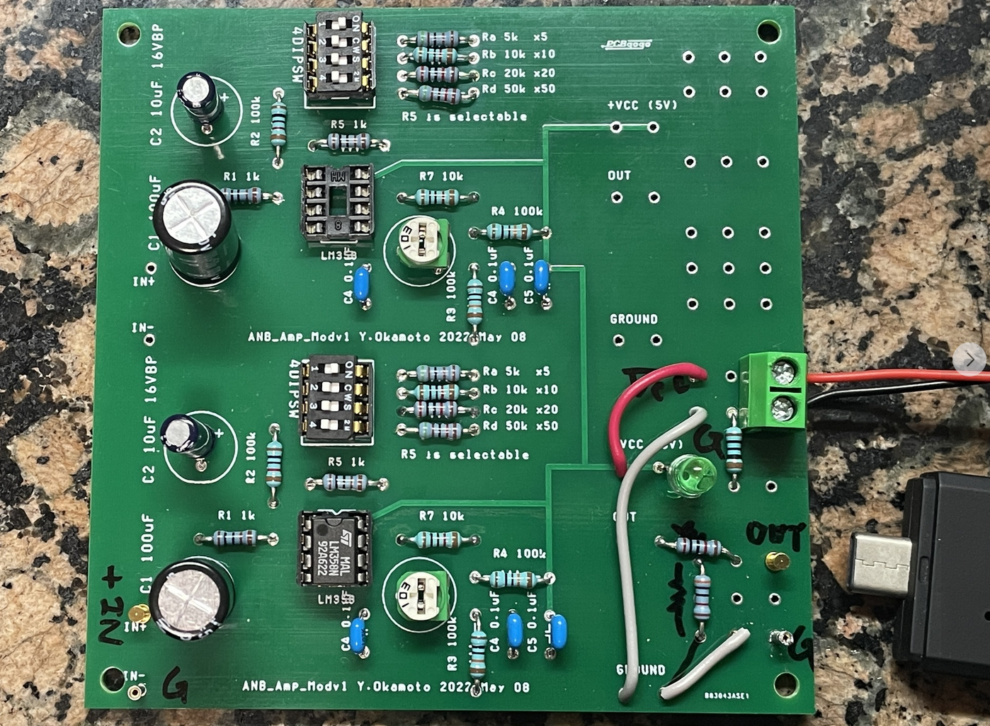
| これが自室の机上で組んだ,ESP32地震計全景です.左から感震
器(振動センサ,固有振動数4.5Hz),アンプ基板(以下のページの回路を修正),補助基板,ESP32LCD付き基板です.アンプ回路は
https://www.zisin.jp/publications/pdf/nf-vol103.pdf#page=6 近くの南海高野線の列車の走行音を2回記録している.記録時間は1秒.ラズベリー・シェイクと同等の地震を記録できる世界最小のデジタル地震計でありながら、それ以上に安価であると自負している! This is a full view of the ESP32 seismometer assembled on the desk in my room. From left to right: seismic sensor (natural frequency 4.5Hz), amplifier board (modified from the following page), auxiliary board, and board with ESP32 LCD. The amplifier circuit is available at https://www.zisin.jp/publications/pdf/nf-vol103.pdf#page=6 The running noises of a Nankai Koya Line train nearby was recorded twice. The time mark is 1 second. I
am proud to say that this is the world's smallest digital seismograph
capable of recording earthquakes as same as Raspberry Shake yet more
than cheaper! |
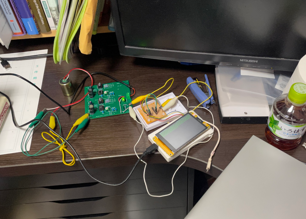
地震計を組んだ自室の机.ごくふつうの環境です.電源はアンプ,基板ともに5V USB電源供給です.基板の方は基板内部で3.3Vに落としているようです.またアンプの出力は基板のADCの規格にあうように,出力最大を,抵抗分圧で3V程度に落しています.
This is a very common environment. Both the amplifier and the board are powered by a 5V USB power supply. The board seems to be powered down to 3.3V inside the board. The maximum output voltage of the amplifier is set to 3V by resistor voltage divider to meet the ADC standard of the board. |
 |
 |
| こちらが以前に附属高の生徒と一緒に地震計を試作したときの回路
(「なゐふる」記事の修正版)を格安中国基板メーカーで,基板にしてもらったもので
す.2ch組んでありますが,本プロジェクトは1chのみを使用.出力の抵抗分圧とか,LEDとかを余った部分で組みました.やはり余ったピンを,余白に
幾つか用意しておいてよかった. I used the extra pins for the output resistor voltage divider and LEDs. It is comfortable that I prepared some extra pins in the blank space. |
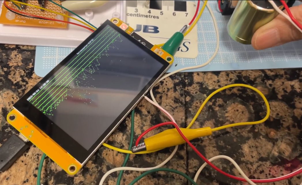
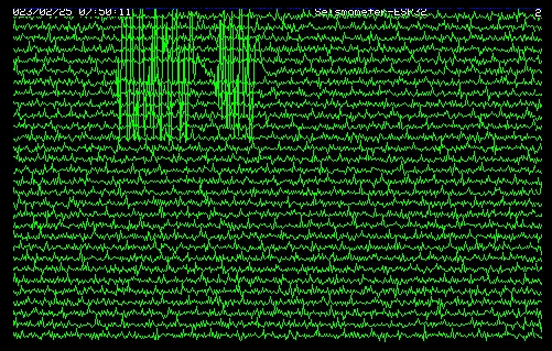
これが最初のAD変換に生データを入れたときのものです.ノイズだらけで実用になりません.タイムマークも埋もれて視えない.信号線は1本約20秒で,全部で30本なので,ちょうど1画面10分ぶんの記録に相当します.
This is the raw data in the first AD conversion. It is so noisy that it is useless. The time marks are also buried and not visible. Each signal line is about 20 seconds long, and there are 30 signal lines in total, which is equivalent to 10 minutes of recording per screen. |
|
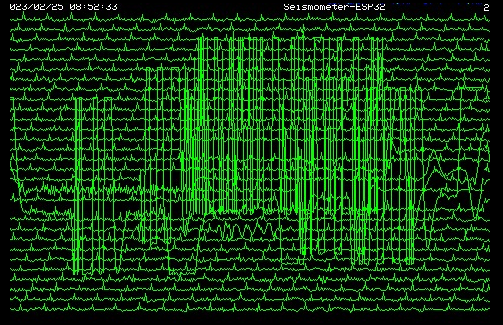 |
| こちらがAD変換をプログラム上で3回行って,その移動平均をデータとして取り出した所.少しマシになりましたが,まだまだ.こ
のあと5個,7個と平均を試し
てみて,最終的に15個まで増やしました.このAD変換の速度は極めて速く,これくらい平均する操作をしても,サンプリング速度にはあまり影響が出なかっ
たのは大変な驚きです.2400円ほどの基板ですが,CPUの処理速度の速さが光ります.
It is a little better, but still not enough. After this, we tried averaging 5, 7, and finally increased the number of averages to 15. The speed of this AD conversion is extremely fast, and it is very surprising that the sampling speed was not affected much by the averaging operation even a cheap CPU circuit 2400JPY. |
最終的に15個のデータの移動平均をAD変換データとして,画面表
示してSDカードにも保存しています.この画面のキャプチャーも約1ヶ月苦しんだあげく
に,何とかBMPファイルで保存できるようになったものです.ただまだアドレスが若干おかしくて,左6ピクセル幅ほどが右側に回り込んでしまっています.
さらに,この画面をFBにアップしようとしましたが,FBに拒否られました.どうもBMPファイルとしてのどこかに欠陥があるようです.画像はPNGに直
してアップしてあります.振動センサを持ち上げたり,部屋で床を振動させたりして,感度を調べています.
Finally, the moving average of the 15 data is displayed on the screen, and is also saved on the SD card. After about a month of struggle, I managed to save this screen capture as a BMP file. However, the address is still slightly wrong, and about 6 pixels wide on the left side of the screen is wrapped around to the right side of the screen. Furthermore, I tried to upload this screen image to my FaceBook, but FB rejected it. It seems that there is something wrong with the BMP file. The image has been converted to PNG and uploaded. I lifted the sensor and vibrated the floor in the room to check the sensitivity. |
 |
 |
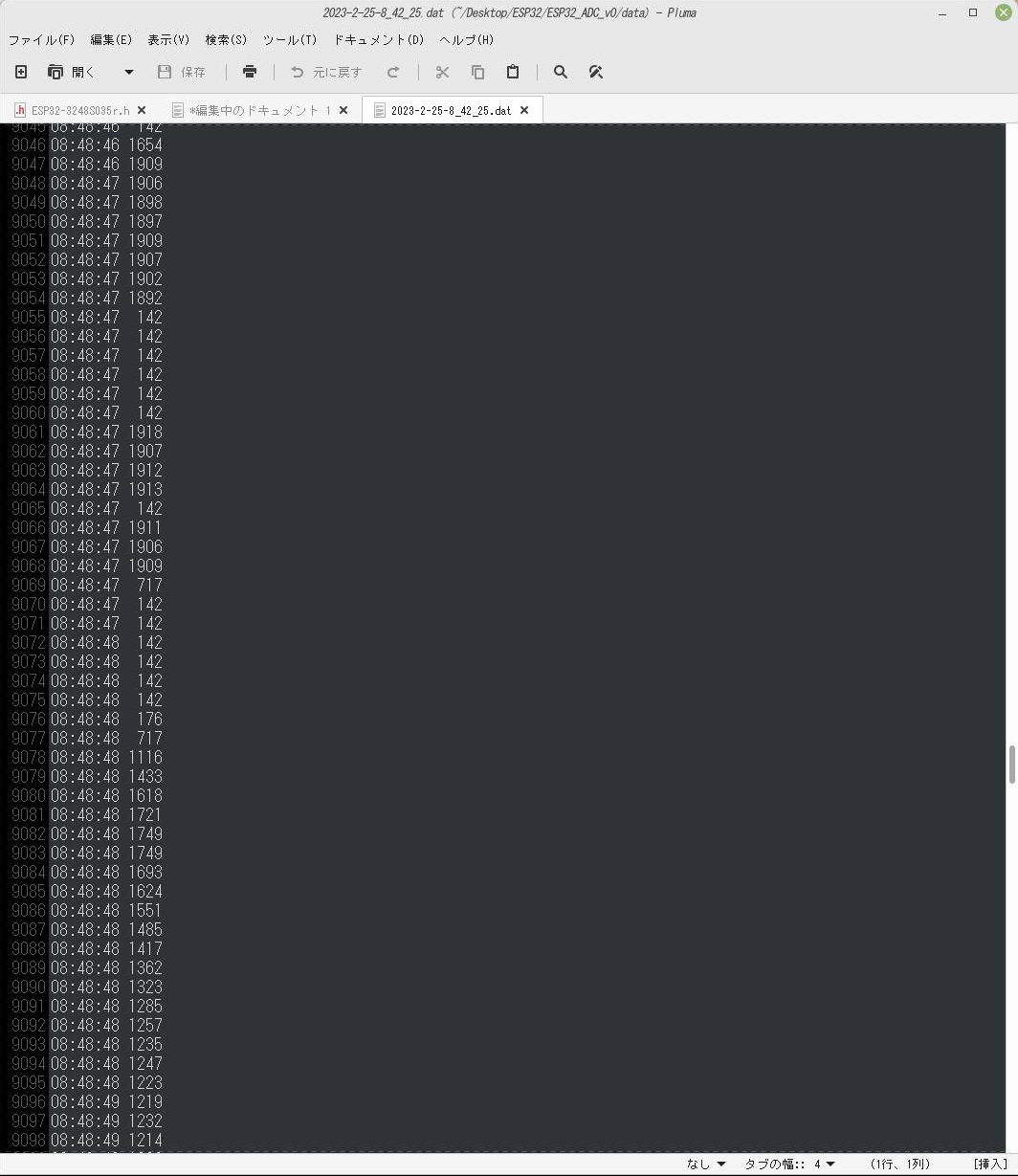
| こちらが同時にSDカードに保存される数値データです.時刻と12ビットAD変換の数値データ(本来0から4096)ですが,mVにして表示しているので,少し小さくなります. こ れはデータのminとMAXを見たいために,センサを手で動かした部分で最低が142,最高が2000弱で,まだおかしいです.このデータはAD変換の値 をmVで表示しています.理論的には0から3000[mv]の間に入り平均が1500[mV]くらいのはずなので,出力の分圧かアンプの調整が,まだおか しい可能性があります.最低が0にならないのはこの基板のADの癖のようです. The time and the numerical data of 12-bit AD conversion (originally from 0 to 4096) are displayed in [mV], so they are a little smaller. This is the part where the sensor was moved by hand to see the min and max of the data. This data shows the AD conversion value in [mV]. Theoretically, the average should be around 1500[mV], falling between 0 and 3000[mv], so the output voltage divider or amplifier adjustment may still be wrong. The fact that the lowest value is not 0 seems to be a quirk of the board's AD. |
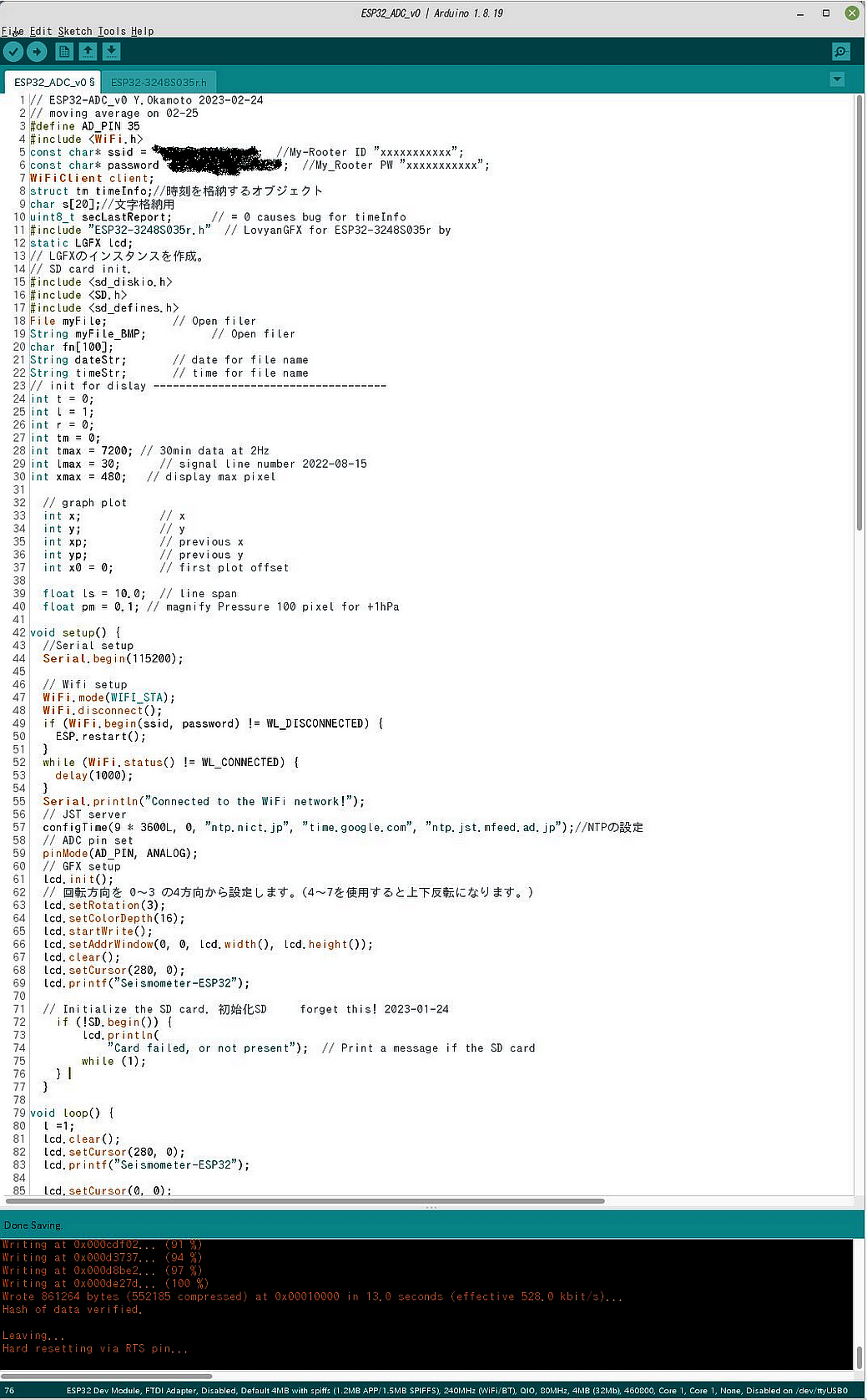
この地震計制御のためのArduinoIDEのプログラムの一部で
す.色んな先達のネットで公開されているソースコードの一部を継ぎ接ぎして,使っていま
す.さっき生のキャプチャー画像を上げてしまって,すぐに気づいて削除しました.自宅のネットのIDとPWはまずいですからね!
It is based on some of the source code that has been published on the Internet by various pioneers. I posted a raw capture of the program a while ago, but I deleted it as soon as I realized it, because my room wifi ID and PW is written on the raw capture image! |
 |
|
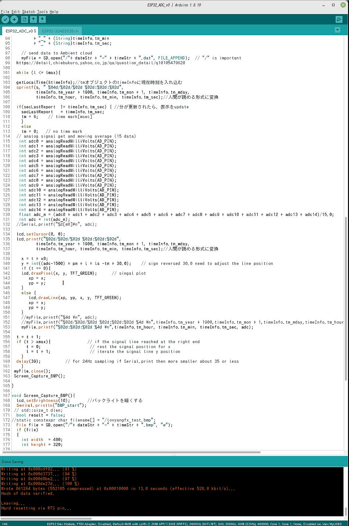
| ADCデータを15個取り込んで,移動平均したデータを表示,書き込みしている部分です.ESP32はwifiがあるのでJSTサーバで時刻を取得しています.シグナルレベルと一緒にSDカードに時刻も書き込んでいます
This is the part where 15 ADC data are averaged, and the moving average data are displayed and written. The
absolute time is written to the SD card along with the signal level.
Because this ESP32 chip can get the Japan Standard Time from their wifi. |
Copyright(c) by Y.Okamoto 2024, All rights reserved.